2-Wire RTD #
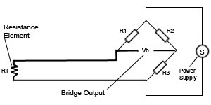
Overview – The simplest resistance thermometer configuration uses two wires. It is only used when high accuracy is not required, as the resistance of the connecting wires is added to that of the sensor, leading to errors of measurement. This configuration allows use of 100Â meters of cable. This applies equally to balanced bridge and fixed bridge system.
3-Wire Circuit
3-Wire RTD #
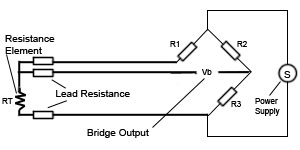
Overview – In order to minimize the effects of the lead resistances, a three-wire configuration can be used. Using this method the two leads to the sensor are on adjoining arms. There is a lead resistance in each arm of the bridge so that the resistance is cancelled out, so long as the two lead resistances are accurately the same.
3-Wire Circuit
In a three-wire circuit two constant current sources are used, in order to compensate for the disadvantages described above for the two-wire circuits. Similar to the two-wire circuit the current source IK2 is used to measure the temperature dependent resistance RT including the lead and terminal contact resistances. The additional current source IK1 together with a third lead is used to separately compensate the lead and terminal contact resistances. Assuming the exact same lead and terminal contact resistances for all three leads, the effect on the accuracy of the temperature measurements can be eliminated. But practice has shown that it is not always possible to assure that the terminal contact resistances are always identical.
4-Wire RTD #
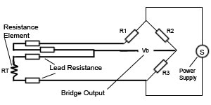
Overview – The four-wire resistance thermometer configuration increases the accuracy and reliability of the resistance being measured: the resistance error due to lead wire resistance is zero. In the diagram above a standard two-terminal RTD is used with another pair of wires to form an additional loop that cancels out the lead resistance. The above wheatstone bridge method uses a little more copper wire and is not a perfect solution. Below is a better configuration, four wire kelvin connection. It provides full cancellation of spurious effects; cable resistance of up to 15 Ω can be handled.
4-Wire Circuit
With the 4-wire configuration, the instrument will pass a constant current (I) through the outer leads, 1 and 4. The voltage drop is measured across the inner leads, 2 and 3. So from V = IR we learn the resistance of the element alone, with no effect from the lead wire resistance. This offers an advantage over 3-wire configurations only if dissimilar lead wires are used, and this is rarely the case.


